How to Design a Sound System for a Church - A Step-by-Step Guide
Designing a church sound system requires completing six sequential steps: acoustic assessment of the space, selection of the system type, speaker placement planning, equipment specification, installation, and calibration. Skipping or reordering any step produces a system that underperforms relative to the room.
Step 1 - Assess the Acoustic Properties of the Space
Acoustic assessment determines how sound behaves in the room before any equipment is selected. The shape of the space, ceiling height, wall materials, and the presence of reflective or absorptive surfaces all directly affect which type of system will perform correctly in that environment.
The primary measurement parameter is RT60 - reverberation time. RT60 is the time, in seconds, for sound to decay by 60 dB after the source stops. For worship spaces, the optimal RT60 range is 0.8-1.5 seconds. Above 1.5 seconds, reflected sound from early words overlaps with subsequent words, degrading speech intelligibility. Below 0.8 seconds, the space becomes acoustically dry and uncomfortable for extended listening. When RT60 cannot be reduced through equipment choices alone, church soundproofing - acoustic treatment applied to walls, ceilings, and floors - is required before the sound system is installed.
Hard surfaces - stone walls, plaster ceilings, glass windows - reflect sound and increase RT60. Absorptive surfaces - upholstered seating, carpet, heavy fabric - reduce it. The acoustic absorption coefficient of each material is used to estimate RT60 before on-site measurement is conducted.
Step 2 - Determine the Size and Seating Layout of the Congregation Area
The seating capacity and physical dimensions of the congregation area determine the required sound pressure level (SPL), the number of speakers needed, and whether a single-point or distributed system is appropriate.
Church spaces fall into three categories, each requiring a different system architecture:
|
Space Category |
Seating Capacity |
Recommended System Type |
Target SPL |
|
Small chapel / prayer room |
Up to 100 |
Single point source (L/R pair) |
85-88 dB |
|
Mid-size worship hall |
100-500 |
L/C/R or single cluster + delays |
88-92 dB |
|
Large worship center |
500+ |
Line array or distributed multi-cluster |
92-95 dB |
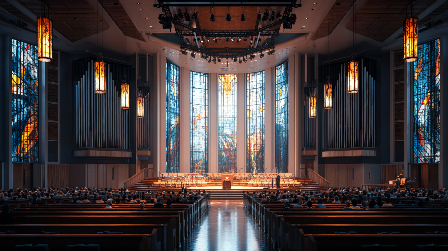
Spaces with balconies require supplemental delay speakers positioned at the balcony fascia. The main system cannot deliver adequate direct sound into the under-balcony zone. The professional standard for coverage uniformity in worship spaces is ±3 dB across the entire listening area.
Step 3 - Choose the Type of Speaker System
Church sound systems are built around one of three configurations: a single point source system, a line array system, or a distributed speaker system. The correct choice depends on room dimensions, ceiling height, and RT60.
A single point source system uses one L/R speaker pair at the front of the room. It is appropriate for spaces with RT60 below 1.2 seconds and ceiling heights up to 6 meters. It provides natural sound localization toward the stage.
A line array system uses a vertical column of speaker elements with narrow vertical and wide horizontal dispersion. It is used in venues with 500+ seats and ceiling heights of 8 meters or more. The narrow vertical coverage minimizes acoustic energy reaching the ceiling and rear walls, reducing reverberation buildup.
A distributed speaker system uses a network of smaller speakers positioned above different zones of the congregation area. Each speaker covers a small area at low output, limiting the total reverberation energy introduced into the room. This configuration is optimal for spaces with low ceilings, balconies, or RT60 above 1.5 seconds.
When RT60 exceeds 1.5 seconds, a distributed system or line array is preferred over a single point source. A high-output single source in a reverberant room increases reverberation with every added dB - making speech progressively less intelligible as volume rises.
Step 4 - Plan Speaker Placement and Coverage
Speaker placement determines how evenly sound is distributed across the listening area. A variance greater than ±6 dB between seating zones makes the system acoustically unusable for speech.
The standard main PA speaker for a worship space has a horizontal dispersion angle of 90° and a vertical angle of 60°. Placement is calculated so that the −6 dB boundary of one speaker's coverage overlaps with the start of the adjacent speaker's zone, ensuring continuity without hot spots.
In rooms deeper than 15 meters, rear seating zones require delay speakers. The correct delay is calculated at 1 millisecond per 30 centimeters of distance between the main cluster and the delay speaker position.
Step 5 - Specify the Equipment List
Equipment specification follows the acoustic and coverage design - not the other way around. The minimum equipment list for a mid-size worship hall includes:
- Main speakers (L/R): full-range, 90°×60° dispersion, minimum 112 dB SPL max
- Subwoofers: one per 250 seats minimum
- Delay speakers: one per coverage zone beyond 15 m from the main cluster
- Digital mixing console: minimum 32 channels for worship band, vocals, and pastor mic
- DSP (digital signal processor): for EQ, delay alignment, and feedback suppression
- Stage monitoring: in-ear monitor (IEM) system or floor wedge monitors for musicians
Amplifier power should be specified at 2-4 times the continuous power rating of each speaker to provide headroom for transient peaks without clipping.
Step 6 - Install and Calibrate the System
Calibration - not installation - is the step that determines whether the system performs to design specifications in the actual acoustic environment.
The calibration sequence must follow this order: acoustic measurement → EQ → delay alignment → level setting → feedback check. Performing these steps out of sequence invalidates the preceding work.
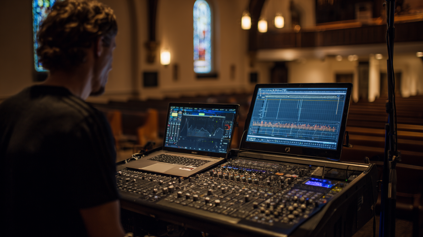
Calibration begins with pink noise fed through the system at a reference level, measured by a calibrated microphone at multiple positions across the congregation area using acoustic analysis software (Smaart, REW, or an integrated DSP analyzer).
EQ during calibration has one purpose: correcting room-induced frequency anomalies and suppressing feedback frequencies. Tonal EQ is performed separately, after the room correction is complete.
The completed installation is verified with two measurements. An SPL test confirms coverage variance does not exceed ±3 dB. A Speech Transmission Index (STI) test confirms speech intelligibility meets the minimum standard of STI ≥ 0.60, as defined by IEC 60268-16. An STI below 0.60 indicates that speech is not reliably intelligible in that zone regardless of volume level.
New York Soundproofing provides acoustic measurement, sound system design, and post-installation calibration for worship spaces throughout New York City and the greater NYC metro area. Contact us for an on-site consultation.